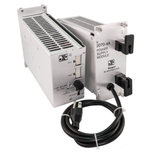
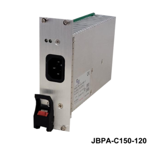
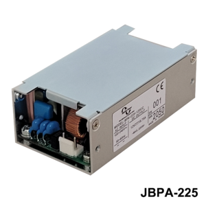
TC 2216 Advanced Transportation Controller (ATC) Power Supply
AC Input / 175 Watt 24 & 48 VDC Output w/ PFC
FEATURES:
- For use in Advanced Transportation Controller (ATC) High Voltage Cabinets
- BABAA Compliant Optionally
- For use in Traffic Intersection Control Systems
- For use in LED Road Signs
- High Efficiency / High Reliability
- For use in existing and new configurations
- Custom Configurations Available
- Description
- Specifications
- Data Sheets
Description
Jasper Electronics Model TC2216-24(HV) component 2216 Power Supply ATC module is fully compliant to the Advanced Transportation Controller (ATC) Cabinet Standard 5301, v02.02, March 18, 2019, and designated as ATC 5301 Model 2216-24-HV. It is available as BABAA Compliant optionally. The features and specifications listed here may be revised as a result of ongoing development testing or additional user requested changes, but as of the user acceptance date of the first article production sample model (Revision code A), changes affecting the form, fit, function or other features outlined in this document shall not be permitted without prior notification to and written approval from the user. Specific design requirements are detailed in the ATC 5301 document.
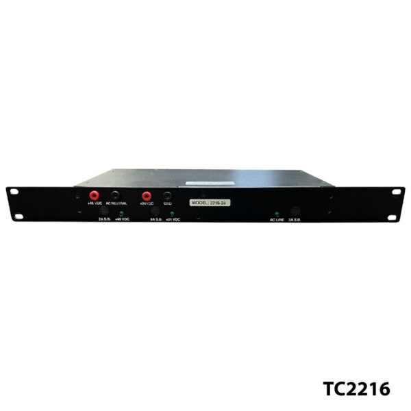
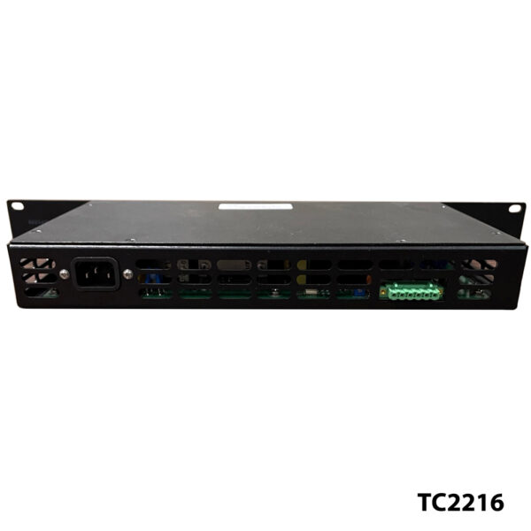
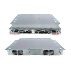
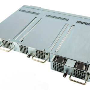
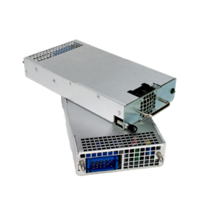
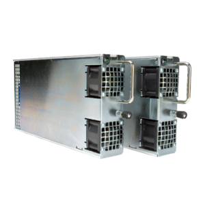
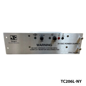
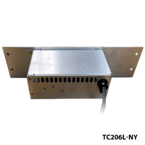
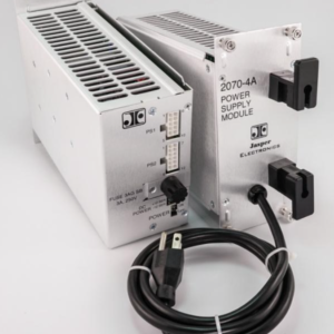
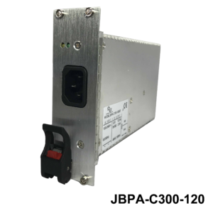
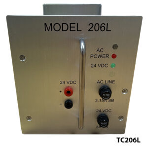
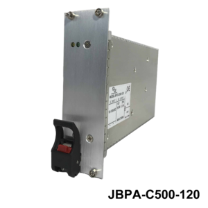
Generally, Model TC2216-24 is a 19.0” rack mounted, fully enclosed 2-output switching power supply capable delivering up to 175 Watts DC and intended specifically for use in ATC High Voltage (HV) Cabinets. These are designed for non-redundant “cold pluggable” installation in the end product. AC input and PE is via a detachable power cord inlet, and DC output power connections are through a 6-circuit connector, both on the rear of the supply as shown. User accessible line-side input and individual output fuses, as well as condition indicator LEDs, are all visible on the front panel. Front panel test points allow the user to verify output voltage set points. Model TC2216-24 is convection cooled, with an extended operating temperature range. It is designed to be directly interchangeable with 2216-24 modules from other vendors.
| INPUT | |
| Voltage/ Current Rating | AC 80-270V,2.6Arms max, 45-65Hz, 10 Phase |
| Fusing | AC 3.00A, 250V delayed action (slow-blow) 3AG 0.25”x1 .25” cartridge type external line fuse provided, operator accessible on the front panel |
| Inrush Current | Soft start (~25°C cold start) 20Apk@ AC 115V |
| Power Factor | >0.95 line PFC typical at 115VAC, full load |
| Efficiency | At AC 115V: >80% |
| Under Voltage Protection | Auto DC output shutdown when AC input falls below safe operating limits. Automatic recovery when input rises to within normal operating range |
| OUTPUT | |
| Model TC2070-4 | |
| Voltage/Current (V/A) | V1 =+48.0VDC 0.0-1.0A V2 = +24.0V DC 0.0-5.0A DC outputs are electrically isolated from AC Mains, Earth Ground and each other |
| Output Voltage Setpoint | Factory preset within ±2.0% of nominal voltage |
| Line Regulation | ±1.0% at the output connection over full AC input range |
| Load Regulation | <±2.0V at the output connection over the full AC input range and 0 -100% output loading |
| Output Sense | Outputs internally sensed |
| Minimum Loading | None required |
| Output Turn-on Delay | <1.00 Sec from AC turn-on @110V AC |
| Over/ Under Shoot | <5% at turn-on or turn-off |
| Stability | <±0.2% output drift after 20 minute warm-up |
| Temperature Coefficient | <±0.02%/°C, 0° - 50°C, after 20 minute warm-up |
| Dynamic Response | Output recovers to within 1 % in less than 500μsec with a 50% load change at a slew rate of 1Nμsec. <±5.0% peak transient deviation |
| Ripple and Noise (PARD) | 300mV max peak-to-peak at the output terminal with a 20 MHz bandwidth limit. May be measured with a 0.1μF ceramic capacitor in parallel with a 22μF tantalum capacitor connected between the measured output and its return |
| Over Voltage Protection (OVP) | Non-crowbar type. Any output exceeding 130%±5% of nominal will cause all outputs to latch off. AC input recycle required to reset |
| Over Current/ Short Circuit Protection | Outputs fuse protected against overload and short-circuit faults |
| Output Fusing | AC 250V delayed action (slow-blow) 3AG 0.25”x1 .25” cartridge type external fuses provided in the(+) output, operator accessible on the front panel V1, 48V DC: 2.0A. V2, 24V DC: 8.0A. |
| Hold-Up Time | Outputs remain in regulation for 50mSec minimum following loss of input power at low line, full load |
| Output Transient Protection | Minimum 1500W voltage transient suppressor |
| SIGNALS, INDICATORS AND CONTROLS | |
| AC Power Indicator | Front panel mounted, single-color LED. Green indicates AC power ON. Off indicates an input or fuse fault |
| DC Power Indicator | Front panel mounted, single-color LED, 1 per output. Green indicates DC power ON. Off indicates an output or fuse fault |
| Output Test Points | Two “banana jack” type test sockets provided on the front panel, color coded red and black. Allows operator to verify output voltage. Mates with 0.175”x0.590” [4.5mmx15.0mm] plugs |
| MECHANICAL | |
| (Refer to JE Outline Configuration Dwg, P/N 04166-000-G.) | |
| Mounting Orientation | 1 U x 19.00” EIA rack chassis designed for horizontal insertion into a dedicated space within an ATC 5301 cabinet |
| Weight | 1.59 Kg [3.50 lbs] |
| Retaining Fastener | 0.450”x0.250” radiusd slots at each corner of the front panel allow for user provided retaining hardware |
| SAFETY, REGULATORY AND EMC | |
| Designed to comply with the relevant industry standards of the authorities having jurisdiction | |
| Touch Current | 1.2mA max @ 50/60Hz, 115V AC per UL 60950 test procedures (Sec. 5.0) |
| Routine Factory Tests | Di-electric strength (hi-pot) to 2121V DC input-to-chassis and input-to-outputs; MegOhm to 500V output-to-chassis |
| OPERATING ENVIRONMENT | |
| Operating Temperature | -34.6° -+165.2°F [-37 .0° -+ 7 4.0°C] ambient at full load |
| Cooling | Convection only |
| Relative Humidity | Up to 95% RH, non-condensing |
| Conformal Coating | All printed circuit board surfaces are fully conformal coated with a UL94V-0 rated material to eliminate moisture absorption that includes a UV tracer |
| Operational Vibration | 0.75G peak, 5 -500Hz along three orthogonal axis |
| Storage Temperature | -40º to +185ºF (-40º to +85ºC) |
| Altitude | Operating to 10,000 ft. Storage to 30,000 ft. |
| MTBF | Designed for 150,000 hrs at 25°C |
| Service Life | 7 years, typical, before replacement should be considered |
| Calibration | Modules will maintain the output voltage and load capacity over the life of the equipment. Annual re-calibration or routine maintenance service is not specified or required |
| INTERCONNECT | |
| J1 AC Input | Recessed 3-circuit, IEC 320/C14 type. User accessible on the front panel. Requires user provided detachable NEMA 5-15 power cord |
| J2 DC Output Connector | 6-circuit (1x6) pcb feed-thru receptacle header, user accessible through a rear panel opening. UL rated 12.0A 250V per contact. UL94V-0 rated PA type insulation material. Phoenix Contact Stecksystem Classic Combicon, pin 1825161. Mates with PC pin 1823422 or user verified alternate plug header CAUTION: In accordance with IEC 61984, COMBICON connectors have no switching power (COC). During designated use, they must not be plugged in or disconnected when carrying voltage or under load J1 Pin# Function 1 +48.0 VDC Output 2 48.0 VDC Ground (Mains Neutral) 3 +24.0 VDC Output 4 Not Used 5 24 VDC Ground 6 Chassis (Earth) Ground |

