TC 250 NEMA Power Supply
AC Input / 132W DC and AC Outputs
FEATURES:
- For use in NEMA TS1 and TS2 cabinets
- BABAA Compliant Optionally
- For use in Traffic Intersection Control Systems
- For use in LED Road Signs
- High Efficiency / High Reliability
- For use in existing and new configurations
- Custom Configurations Available
- Description
- Specifications
- Data Sheets
Description
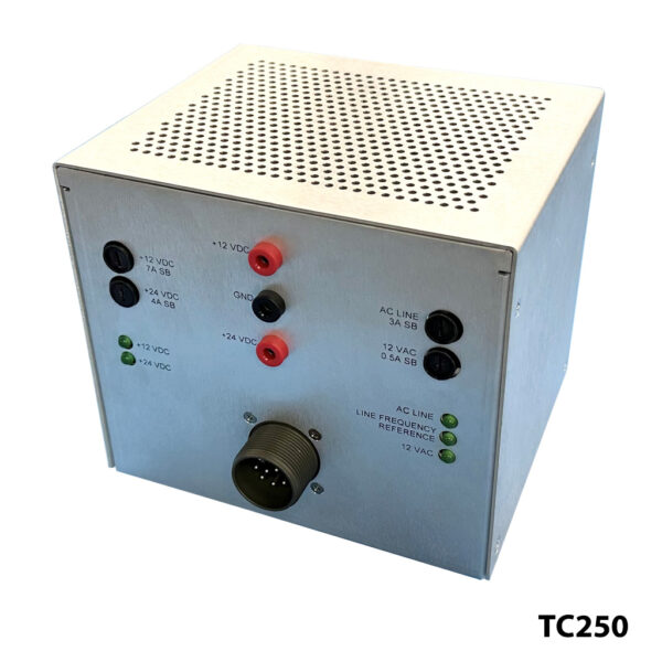
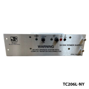
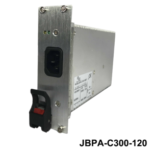
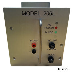
Jasper Electronics (JE) model TC250-055-G is a component TC250 NEMA Power Supply module designed to meet or exceed the requirements of NEMA TS 2-2016 V03.07, as required for TS-2 Type 1 and TS-2 Type 2 traffic control cabinets that incorporate Bus Interface Units. This unit is available as BABAA Compliant optionally. TC250-055-G is rack mounted and fully enclosed, providing up to 132 Watts to two regulated DC outputs and a single unregulated AC output, and include a line frequency reference for use in detector racks, load switches and auxiliary components of traffic control cabinets.
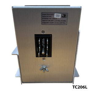
TC250 modules are convection cooled, with an extended operating temperature range. These units are designed for non-redundant “cold pluggable” installation in the end product. AC input, PE, DC power output and signal connections are via 12-circuit connector on the rear of the chassis. Line-side input fuse and individual output fuses are user accessible on the front panel, adjacent to I/O LED condition indicators. Changes affecting the form, fit, function or other features outlined in this document shall not be permitted without prior notification and approval of the user.
| INPUT | |
| Voltage/ Current Rating | AC 90-250V, 47-63Hz, 1.6A max, Single Phase |
| Power Factor | >0.98 line PFC typical at AC 115V, full load |
| Fusing | AC 3.0A, 250V delayed (slow-blow) action 3AG 6.35x31.75mm glass cartridge type external line fuse provided, operator accessible |
| Inrush Current | Soft start (~25ºC cold start) 30Apk @ AC 115V |
| Efficiency | At AC 115V: >84%. |
| Under Voltage Protection | Auto output shutdown when AC input falls below safe operating limits (75V±4V AC). Automatic recovery when input rises to within normal operating range (85V±4V AC) |
| OUTPUT | |
| Model TC250-055-G | |
| Voltage/Current (V/A) | V1 12.0V DC / 5.0A V2 24.0V DC / 3.0A V3 ~ 12.0V AC / 0.25A @ 120V AC nom. ~ 7.5V AC min. @ 89V AC input |
| Output Voltage Setpoint | Factory preset within ±2.0% of nominal voltage |
| Line Regulation | <±2.0% at the output connection over the full AC input range and 0 – 100% output loading |
| Load Regulation | V1: 12V±1.0V; V2: 24V±2.0V |
| Minimum Loading | V1: 0.5A; V2: 0.3A |
| Output Turn-on Delay | < 1 Sec from AC turn on at 25ºC |
| Over/ Under Shoot | None at turn-on or turn-off |
| Stability | <±0.2% output drift after 20 minute warm-up |
| Temperature Coefficient | <±0.02%/°C, 0° - 50°C, after 20 minute warm-up |
| Ripple and Noise (PARD) | 2.0V max peak-to-peak / 500mV RMS nominal at the output terminal with a 20MHz bandwidth limit. May be measured with a 0.1μF ceramic capacitor in parallel with a 22μF tantalum capacitor connected between the measured output and its return |
| Over Voltage Protection (OVP) | Non-crowbar type. V1_out rising to 125%±3% of nominal will cause V1, V2 outputs to latch off |
| Over Current/ Short Circuit Protection | Outputs fused |
| Over Temperature Protection | Internal temperature sensing. Causes output to shut down. Automatic recovery |
| Output Transient Protection | Minimum 1500W voltage transient suppressor provided |
| Output Fusing | AC 250V delayed (slow-blow) action 3AG 6.35x31.75mm glass cartridge type external fuse provided in the (+) outputs, operator accessible. V1: 7.0A; V2: 4.0A; V3: 0.50A |
| SIGNALS, INDICATORS AND CONTROLS | |
| LED Indicators | Front panel mounted, single-color LEDs for input power, V1, V2, V3 outputs and line frequency ref. Green indicates input and outputs are functioning within specifications, off indicates a fault |
| Output Test Points | Three “banana jack” type test sockets provided on the front panel, color coded red and black. Allows operator to verify V1, V2 output voltage |
| Line Frequency Signal | A terminal on the I/O connector provides a 60Hz AC Line Frequency reference rated at 50mA |
| MECHANICAL | |
| (Refer to JE Outline Configuration Dwg, P/N 044266-000-G.) | |
| Weight | 1.68Kg [3.70lbs] |
| Size | Refer to the JE Outline Dwg or the Mechanical Outline in this data sheet |
| OPERATING ENVIRONMENT | |
| Operating Temperature | -34.6º – +165.2ºF (-37.0º – +74.0ºC) ambient at full load |
| Cooling | Convection only |
| Relative Humidity | Up to 95% RH, non-condensing |
| Operational Vibration | 0.75G peak, 5 – 500Hz along three orthogonal axis |
| Storage Temperature | -40º to +185ºF (-40º to +85ºC) |
| Altitude | Operating to 10,000 ft. Storage to 30,000 ft. |
| MTBF | Designed for 150,000 hrs at 25°C |
| Calibration | Modules will maintain the output voltage and load capacity over the life of the equipment. Annual re-calibration or routine maintenance service is not specified or required |
| Service Life | 7 years, typical, before replacement should be considered |
| INTERCONNECT | |
| Input/ Output Connector | Amphenol MS3102 A18-PW:10 Circuit, 16 6A Male Contacts (13 amps/pin) |
| Note: Use of the specified mating connector is recommended. Refer to the Mechanical Outline Dwg. for pinout ID | |
| Pin # | Function |
| A | AC Neutral |
| B | Line Frequency Ref. Output |
| C | AC Line Input |
| D | +12VDC Output |
| E | +24VDC Output |
| F | Reserved |
| G | Logic Ground |
| H | Earth Ground |
| I | +12 VAC Output |
| J | Reserved |
| SAFETY, REGULATORY AND EMC | |
| EMC designed to comply with the relevant industry standards of the authorities having jurisdiction - typically UL 60950-1, CSA 22.2 and IEC 60950 |
|
| Touch Current | 1.2mA max @ 50/60Hz, 264V AC per UL 60950 test procedures (Sec. 5.0). |
| Routine Factory Tests | Di-electric strength (hi-pot) to 2121V DC input-tochassis and input-to-outputs; MegOhm to 500V output-to-chassis |

